
G503 WWII 1943 Willys MB Jeep Re-Wire or Wiring up your Jeep
This article shows the wiring or re-wiring steps for you early to mid WWII Willys jeep with a new wiring harness.


|
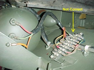
1. Over the years as the wiring on a jeep deteriates it is replaced with wiring that is not correct. Rewiring your jeep can be a one man job, but having another person to compare your understanding can be worth while. In this article, we will describe the steps on how to rewire your wwii 42-43 jeep. |
|
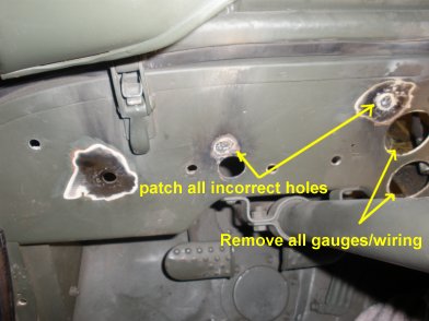
2. The first thing you want to do is remove all wiring and pull out your Fuel, Oil, Temperature, Amp gauges. Also remove the speedometer and ALL existing wiring. If you are going to re-use any wiring be sure to LABEL them. |
|
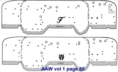
3. The Firewall holes are different between the Willys and Ford tubs. You can get all the sizes of these holes from the All American Wonder Vol I book on page 80. |
|
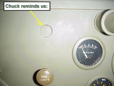
4. Chuck Lutz shows a pic of a GPW dash with the "knockout" plug still in the dash. GPWs starting around Mar/Apr 1943 had that for the cold weather starting setup and should not be filled in. If the hole plug is missing, a slightly larger disc can be tacked on from the rear to mimic the original still in place. |
|
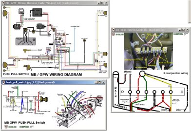
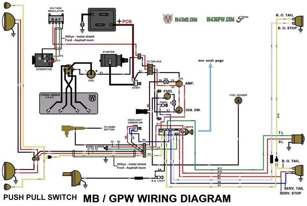
5. To start, you want to print the wiring diagram, the main switch diagram and a sample color picture of the 6 post junction from Print All (pdf). |
|
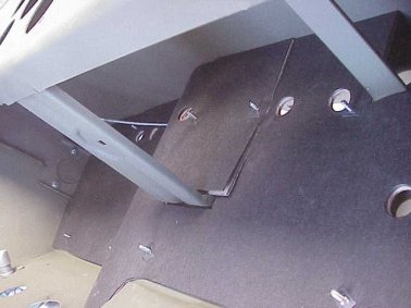
6. Next, install the firewall padding kit under the dash. This firewall kit part # A3132 01 comes with the hardware needed to install. Getting under the dash can be a pain, but this item should be applied for safety. |
|
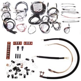
7. The wiring master kits come with all the wiring parts you need to wire your jeep and is part # A2002 B MK. These kits from MV Spares or Vintage Wiring of Maine are quality kits. The diagrams are poor in the kits, but the wires are all labeled and placed in seperate bags for easy application. |
|
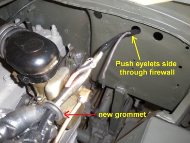
8. To start the wiring, find the Main switch harness. It is the largest bag in the kit. Lay the wire out and the end with the eyelets, push through the firewall and pull down under the dash and stop at the Black w/red tracers wire. Install a new grommet from the other side and push it through and install on the firewall. |
|
9. IMPORTANT! It is critical to wire up your main switch A1345 first under the dash before you pull it tight to mount to the dash. This is the most comfortable way to reach everything. Once you pull the harness and mount on your dash you are forced to be bent over to make adjustments. |
|
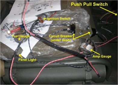
10. With the main switch wired up, we found it easier to layout all the other connections from the diagram in order to account for all the wires. The diagram gets a little confusing because there are wires that come together as one, but the diagram looks like there are two (ie red Amp gauge wires). If you layout, and wire up the Ignition switch, Panel light switch A1333, fuel gauge A8184, circuit breaker A1733 K, and amp gauge A8186 to the main switch, it then becomes easy to put it into the dash and mount. |
|
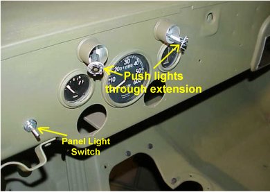
11. Next, install the panel lights which are pretty easy to connect and install on the dash. Follow the diagram and wire up the switch. Then put the extensions on the dash and push the wired bulb sockets through the extenssions. |
|
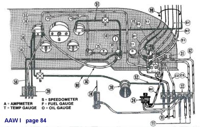
12. You can now follow the wiring diagram and start installing your gauges and switches into the dash. The ALL AMERICAN WONDER Vol I (Page 84) shows a nice picture of the back of the dash. This diagram will help you check the connections prior to installing into the dash. |
|
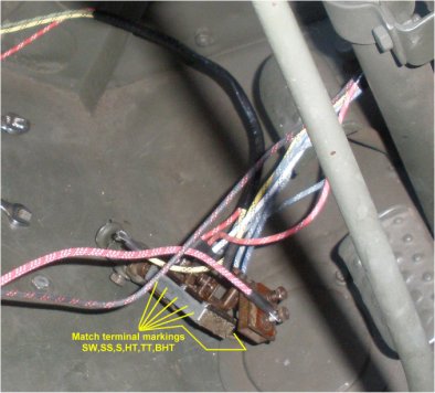
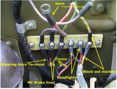
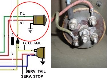
13. With the wiring complete on the Dash side, move to other side of the firewall and wire up the 6 post junction. Follow the diagram it is pretty straight forward. When you complete the six post wiring, then connect the horn line on the sterring box, and the connect the Master Cylinder Brake light switch leads (green and red). |
|
14. Next, wire up the Headlight dimmer switch A12056 down on the floor panel as shown here. |
|
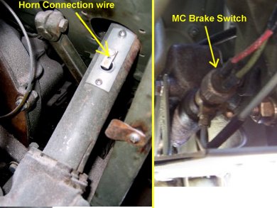
15. Now connect the Horn wire to the steering box, and the two connections to the Master Cylinder brake switch A1271 |
|
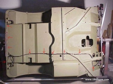
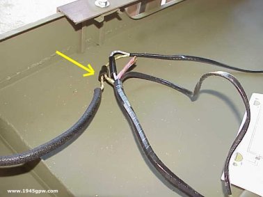
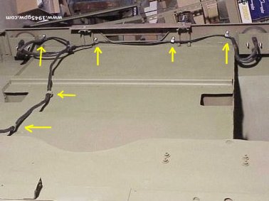
16. Now run the main harness back to the tail light section. There are a couple TABS on the tub and the other clips should help you secure the wire to the tub. The red arrows in this diagram show you where there is a tab or where a clip should be installed. These holes for clips should be present. |
|
17. Next connect the tail wires with the connectors that came in the kit. |
|
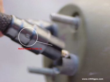
18. The rear connectors can be a little confusing. There is a notch in the pilot bushing that allows you to twist and connect. If you don't line up the notch with the pilot, it will get locked up. |
|
19. Once you have the tail light wires connected, then wrap some electrical tape around the connectors to protect the connectors from potential water and dirt. |
|
20. Now verify your clips and tabs have the wiring secure to the tub. Also, take the Trailer socket wires and push them through the driverside tool box bottom. |
|
21. Next, wire up your trailer socket A6019. The ground wire can be black or blue. The trailer socket should be clearly marked for the other two connections. |
|
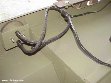
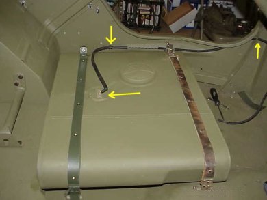
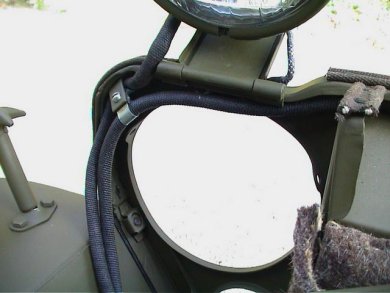
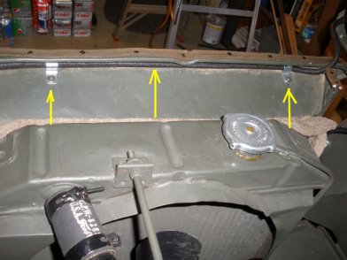
22. Now wire up the Fuel Tank sender wire. This is a simple connection to the sender, and will follow the driver side of the tub into the dash and to the fuel gauge A8184 - 6v. Note, the connections and route in the picture. |
|
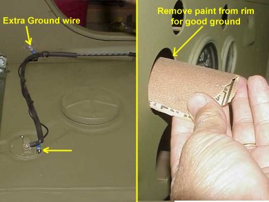
23. The Fuel gauge requires a very good ground and here are two ways to do it. First, you can add an extra ground wire (as shown on the left) and connect it from one of the sender screws to the side of the tub (where a footman loop is connected) and Second, sand down to bare metal around the Fuel gauge hole so that the casing of the fuel gauge will utilize the ground as well. In addition, DO NOT paint the casing to the fuel gauge otherwise you will lose your ground connection. |
|
24. Now we move to the wiring the head lights starting with the drivers fender from the six post junction. Here you see the connection to the two post junction for the headlights and marker lights. |
|
25. The headlight wiring will follow the top of the grill and connect with clips to the grill as shown. |
|
26. The passenger headlight line will follow the top of the grill and connect over on the passenger headlight bucket. There are two clips in the top of the grill to hold the line in place. |
|
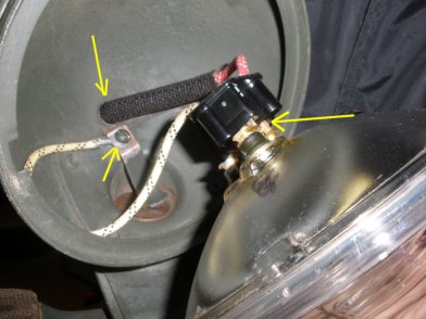
27. To wire up the headlights, run the wire loom through the hole in the back of the bucket, and connect the yellow ground wire to the screw shown. Then connect the 3 prong connector to the headlight. Push the headlight into the bucket and connec the retainer. |
|
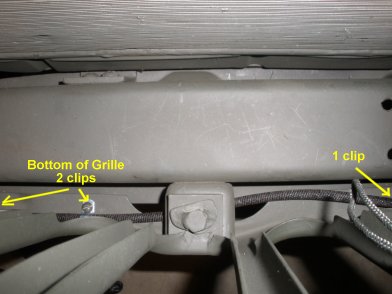
28. Now run the Black Out Marker light wire on the bottom of the grille. There should be 3 holes for clips. This picture is looking down on the line being run across the bottom. |
|
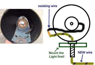
29. Wiring the marker lights need to be done while the mark housing is installed. With the Marker lights in place, run your marker light wire through the screw housing and pull through. You should have an existing wire from the BO light that will need to be connected to the new wire you just brought through the housing. Place a small shrink wrap piece away from the two wires you are about to connect. Wrap these two wires together (or solder). The move the shrink wrap around the connected wires for protections. |
|
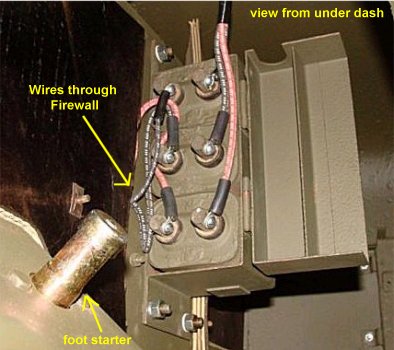
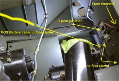
30. Next, move to the filterette on the inside dash on passenger side. You should have two wires (red/black) that connect to the filterette, and red/black wires that need to go through the firewall. |
|
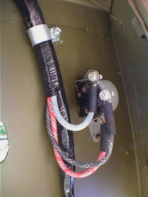
31. Pulling the wires through the firewall from the filterette, connect to the 2 post junction, and the third wire will connect to the foot starter WITH the cable from the POS Battery post. DO NOT CONNECT TO BATTERY YET. |
|
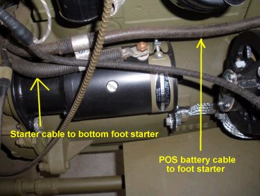
32. Finish the foot starter by connecting the bottom connection to the starter. |
|
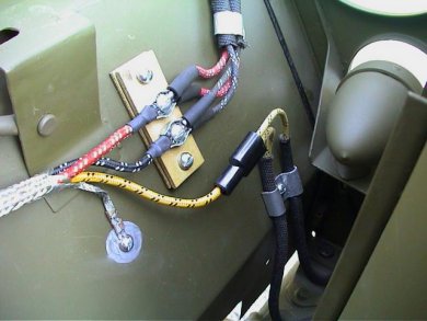
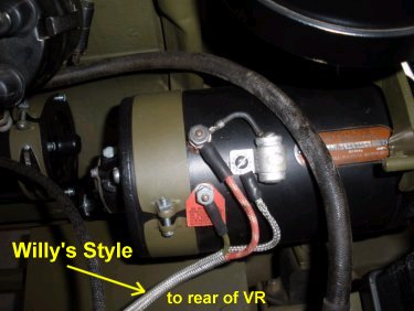
33. Next connect the generator wires to the generator. Here the Willy's style ground sheath is shown. and will be connected to the rear of the Voltage Regulator housing bolt. |
|
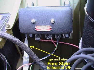
34. Now install the wires to the regulator. Previous picture shows the Willy's style, the Ford style is flat ground cable and was connected to the front Voltage Regulator housing bolt |
|
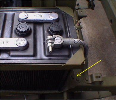
35. Now connect the battery Ground cable. It will go to the shock mount for Fords, and the battery tray for Willys |
|
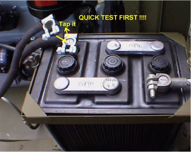
36. QUICK TEST FIRST! To ensure you have everything hooked up correctly, we will tap the POS battery cable to the battery. You want to have someone watch the AMP Gauge and see if it goes negative. If it does, then you have a wire hooked up incorrectly and the system is shorting out. If everything looks ok, continue testing. |
|
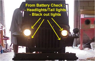
37. TEST MAIN SWITCH: With the POS battery cable connected (AND READY TO PULL OFF QUICKLY), start testing your main switch and lights. Note: it only takes about 10-15 seconds for wires to fry if they are connected incorrectly. So any signs, SMELL, SOUND, VISUAL smoke, disconnect the batter quickly. Otherwise go through Black out lights, headlights/ tail lights testing. |
|
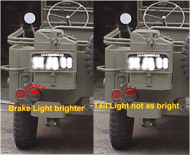
38. TEST BRAKE LIGHT: with ignition on, and main switch pulled all the way out, press your brake and see if the light comes on, if so you are good. If not, your brake light switch could be bad, or the wires were not connected. |

|
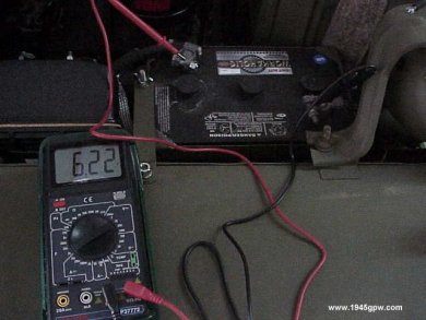
39. Test the voltage out of the regulator by using a multimeter, set to max of 10 volts. Voltage meter on battery posts while runninig. |
|
40. Problems? Here are some testing techniques. |

|
41. Do the final testing. Have one person hold the battery cable on POS terminal and go through the steps in the Push Pull main switch verifying the lights. If all looks good, then you can install the battery and start the jeep up and test the voltage back to the battery from the regulator. Always keep an eye on the Amp Gauge. |
